Asus Z9PE-D8 WS Dual Socket Workstation Motherboard Review
Chris Hadley / 13 years ago
Taking our first look at the board we can see that its sheer size means that it does not conform to normal ATX standards and this would mean that a suitable case that can house an EEB form factor would be required for its use.

The specific nature of this board means that we find two CPU areas each for a socket 2011 processor and each with a quad channel memory bank surrounding them.
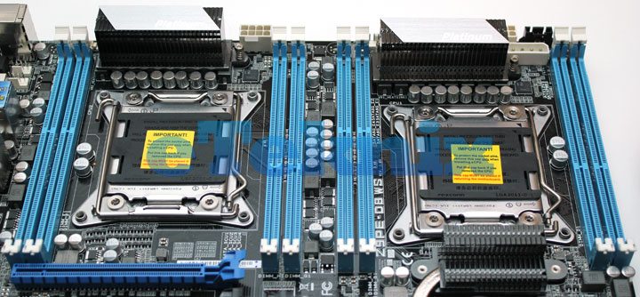
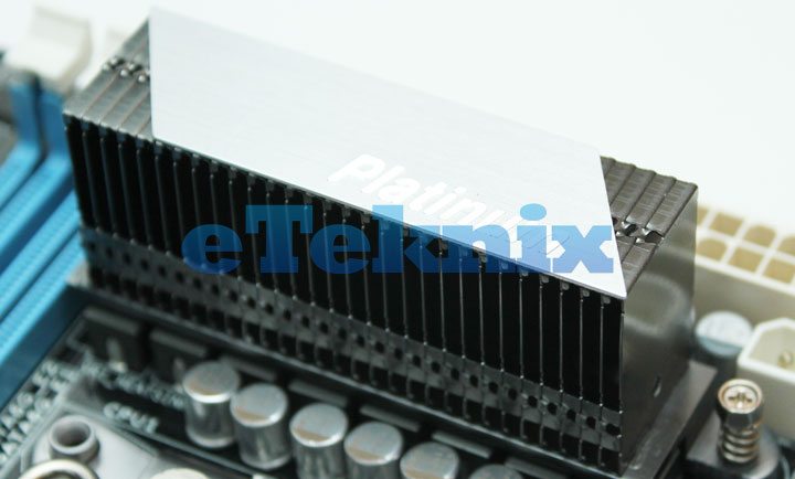
Above each socket on the separate VRMs is a passive heatsink which rather than having a fancy design to what we normally see, takes the practical approach to do as it needs to and each one is topped off with a metal cap with ‘Platinum’ printed on the bottom right corner.
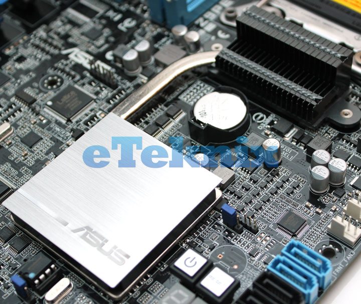
Further down the board below the right hand socket we find the chipset cooler which like the VRM coolers, isn’t overly elaborate but does have a more conservative design with a brushed aluminium top to the cooler with the Asus branding on top. This board runs on the Intel C602 Express chipset which is able to handle multiple processors and large number of SATA ports with their multiple features that we will delve a little further into later on.
Moving onto the memory modules, the board can support two types of memory across its eight DIMMs. At its maximum it can support 256Gb of DDR3 800/1066/1333/1600 Registered memory which will require CPUs with compatible memory controllers to run or alternatively will take upto 64Gb of ECC or non-ECC un-buffered DDR3 1066/1333/1600. Depending on the installed processors and their limits you can force the memory to higher speeds if they support it. For example our memory that we use is 2133MHz, but do to a memory controller limitation on our Xeon processors, we are only able to run the memory at 1600Mhz.
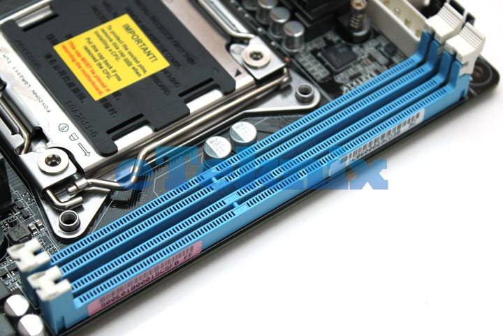
In between the two sockets we find the other half of the quad channel memory bank for the right hand CPU and two of the DIMMs for the left hand CPU.
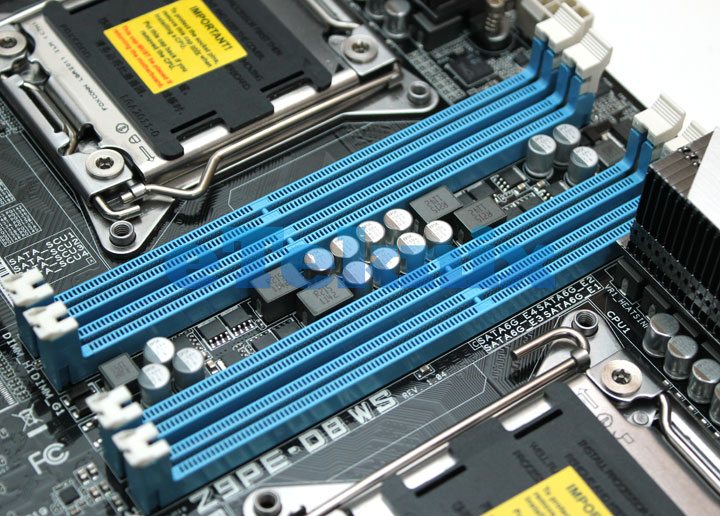
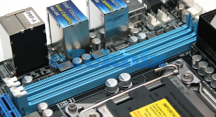
To the far left we then find the last two of the DIMMs for the left hand processor.
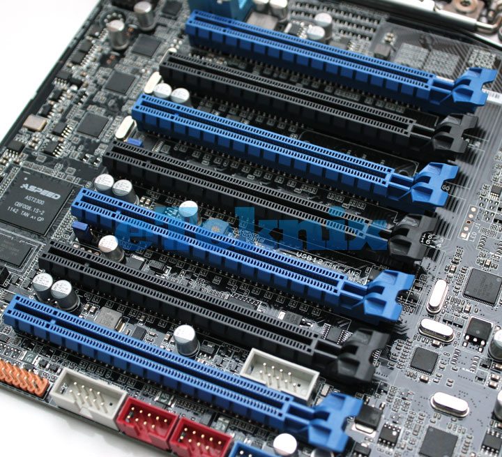
Going over to the expansion sockets we find that the board has a total of seven PCIe 3.0 ready lanes. With this board having dual processors, the way in which the PCIe lanes run is very much different to a single socket board. Depending on which slot a card is inserted into, either of the two processors will control that particular lane. Considering the complexity of the configuration, the manual does give a concise instruction on the speed the lanes will run at for the best performance.
Moving slightly further down the board, we find all of our USB and front panel connectors. There is a total of four USB 2.0 headers, each supporting two USB ports per header and also a USB 3.0 native header included too. Just between these is a 1394 FireWire header and just to the right are the typical front panel headers for power buttons and LEDs.

Further along the board we find a front panel USB3.0 header, two more USB2.0 but this time we see that they are physical ports instead of headers, there are also tow system/ chassis fan headers, fours SATA ports which we will go into further down, and then finally the standard front panel headers (white) and auxiliary front panel headers which give connectivity for the likes of LAN status LEDs and chassis intrusion LEDs.

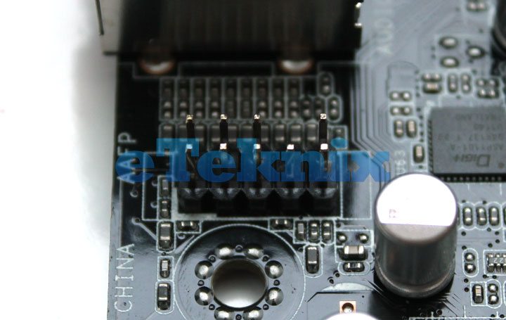
Further up the board next to the rear I/O panel we find the front panel HD audio header.
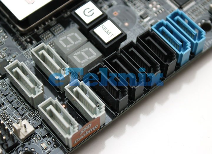
Moving over to the storage side of the board you will notice that there are more SATA ports than one would normally find on a consumer level board. On here we find that there are a total of fourteen SATA headers 10 of which are controlled by the Intel C602 chipset and and additional four headers seen below in grey which are driven by the Marvell 9230 controller. Each of the SATA headers are colour coded to define them into their groups and to indicate their connection speed from the rest.
The top two blue headers driven by the C602 chipset are SATA 6Gbps and support RAID 0, 1, 5 & 10, the first four of the eight black headers are also Intel controlled, running at SATA 3Gbps supporting RAID 0, 1, 5 & 10. The four grey headers as mentioned run off the Marvell 9230 controller and in addition to supporting RAID 0, 1 & 10 also have disk write caching capability as highlighted by the sticker that we can see affixed to the side of the ports.
At the bottom of the board amongst the front panel headers there are the additional four Intel controlled SATA 3Gbps headers which work in coalition with the other four over to the right of the board. These headers here also support Intel SCU for SAS and SATA drives.

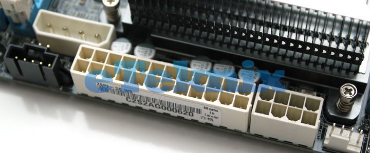
With the processor sockets taking up the width of the board the 24 pin ATX power connector has been moved up to the top of the board with the first of the two 8 pin power connectors located in the same area for the primary CPU socket. In this area is also the EZ_plug molex power header which gives the board extra power when using multiple GPU configurations.
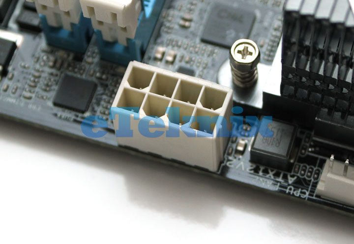
Above the second CPU socket there is an additional 8 pin power connector providing the second processor with the power that it requires.
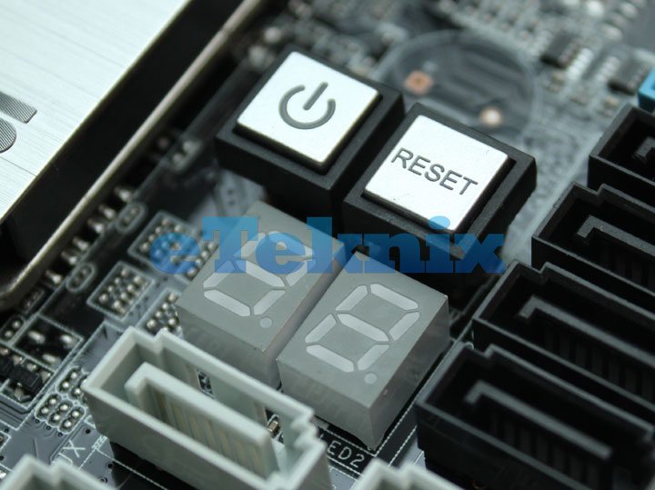
Between the chipset cooler and the main bank of SATA headers we find the on board power and reset buttons and below this the debug led for diagnosing any problems on the board.
Finally, moving round to the rear I/O on the motherboard there are a total of six USB 2.0 ports, two USB 3.0 ports, a legacy PS/2 keyboard/mouse combo port, dual Intel gigabit lan, 8 channel analogues audio and finally and optical S/PDIF digital output.

