Corsair RMi Series RM650i Fully-Modular Review
Peter Donnell / 10 years ago
Test Procedure
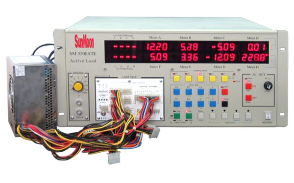
At eTeknix we take the power supply testing procedure very seriously and have invested a lot of resources into acquiring the appropriate testing equipment. For all power supply reviews we test the power supplies with dedicated power supply testing equipment. This means we are able to get the most accurate results from our testing as opposed to using software benchmarks (such as OCCT) or multi-meter readouts which are broadly inaccurate.

Our test machinery is as follows:
- Sunmoon SM-5500ATE Active Load Tester (1200W rated)
- Stingray DS1M12 USB Oscilloscope
- Voltcraft DT-10L laser tachometer
The eTeknix test procedure involves:
- Testing each power supply at 20/40/60/80/100% load (with balanced load across all rails) and measuring PFC (power factor correction), efficiency (actual power divided by power “pulled at the wall”) and voltage regulation (deviance from expected voltages of 3.3/5/12 on the main rails).
- Measuring ripple with an oscilloscope at 20/40/60/80/100% load.
- Measuring fan speed after a stabilisation period of five minutes at each load scenario using the Voltcraft DT-10L laser tachometer and a reflective strip on the fan.
- Testing each power supply’s OPP (Over Power Protection) mechanism and seeing how many watts each power supply can deliver before shutting down
Other things to consider are that
- We recognise that a single yellow 12 volt cable can provide only 6 Amps before overheating (which corrupts voltage regulation and efficiency) and so we used an adequate number of cables for each power supply to ensure there is not efficiency loss from poor cables selection
- Our Sunmoon SM-5500ATE power supply tester is not capable of testing more than 300W on each of the 12 volt rails so where a power supply provides more than 300W on a 12 volt rail that power is distributed over multiple 12 volt rails on the load tester. For example a power supply with one 12 volt rail supplying 750 watts would be spread equally over three 12 volt rails on the load tester, a power supply with two 450W 12v rails would be spread over four 12v rails on the load tester, two 225W 12v rails for each of the 12v rails on the unit.
- We use the same time scale and horizontal millivolt scale on our oscilloscope for all ripple tests, that is a 20ms T/DIV (horizontal) and a 0.02 V/DIV (vertical) meaning the scale is from -80mV to +80mV, ATX spec dictates that the 12v rail must fall within 150mv of ripple and the 3.3/5 within 50mv so that scale allows us to include both 150 and 50mV peaks. (Some older PSU reviews use different scales which were later ditched as the visual representation they give is inadequate, in these reviews written measurements are provided only).
- Deviance is the terminology used to represent the way voltages diverge from the expected values


