GIGABYTE MZ31-AR0 (SP3 EPYC) Server Motherboard Review
Bohs Hansen / 6 years ago
A Closer Look & Layout Analysis
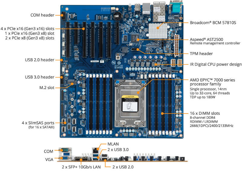
We had a look at the general feature on the first page and now its time to take a closer look at where everything is located.
Power Connections and Onboard Buttons
A server motherboard usually doesn’t come with any onboard buttons, they simply aren’t needed here. Not in the same way they are on an overclocking board, for example. We do have power connectors though, and they’re all in the top corner behind the IO area. There are two 8-pin and one 24-pin power connectors to supply enough power to all components.
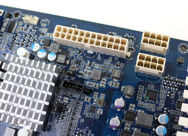
All the caps and power regulators on the board are high-quality as you’d expect them to be.
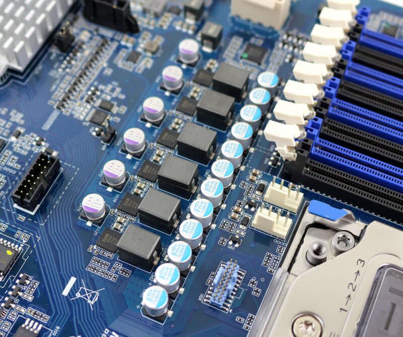
They’re located all around the main CPU and memory area, making sure all the components get a stable power delivery.
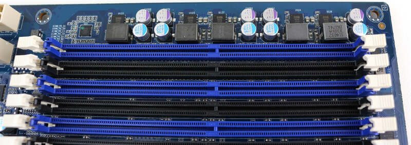
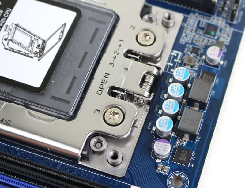
Processor and Memory Sockets
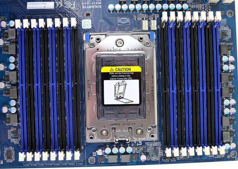
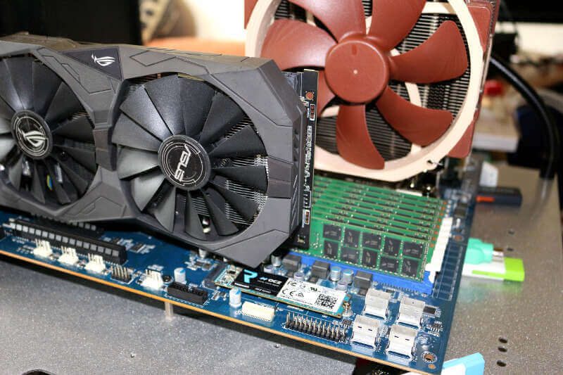
Server motherboards have a generally different layout as they need to fit into rack chassis rather than desktop setups. EPYC boards such as this look different tho as there are so many core component options. The CPU and memory area takes up nearly half the PCB space.
We can also spot the two 4-pin fan headers for the CPU cooler right next to the CPU socket.
Storage Connectors and USB Headers
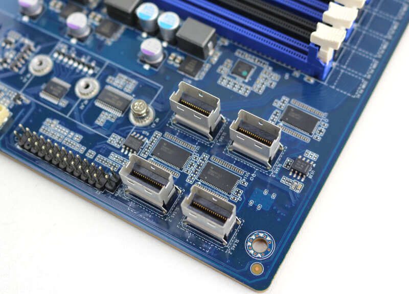
The storage connectors are located at the inner bottom corner. There are four SlimSAS ports which each supports four SATA drives. A great setup choice over adding 16 SATA ports on the board. Not only would it take up a lot of space, the SlimSAS setup allows for a much cleaner cable setup. Also, I really wouldn’t know where to put 16 standard SATA ports on this motherboard. There simply isn’t the space for them.
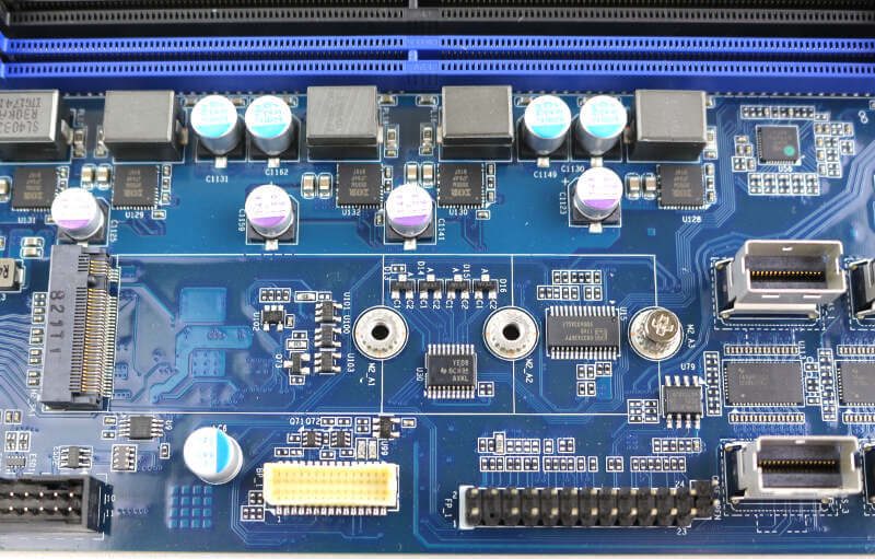
The PCIe 3.0 x4 M.2 slot is located right next to the SlimSAS ports which keeps all storage options close by each other.
PCI-Express Slots
With 128 PCIe lanes from the CPU, there’s enough to bandwidth to run all expansion slots at full speed. The MZ31-AR0 motherboard has five x16 and two x8 slots available which allow you to install a lot of cards without any worry about performance throttling.
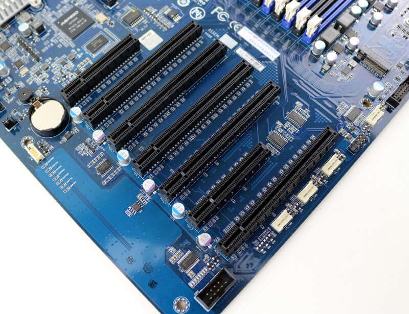
It should be noted that you won’t be able to install longer add-in cards in a lot of the slots. At least not unless you use riser cards or cables. HHHL cards will fit with no issues, but graphics cards, for example, can be too long to fit in anything but the bottom x16 or x8 slots.
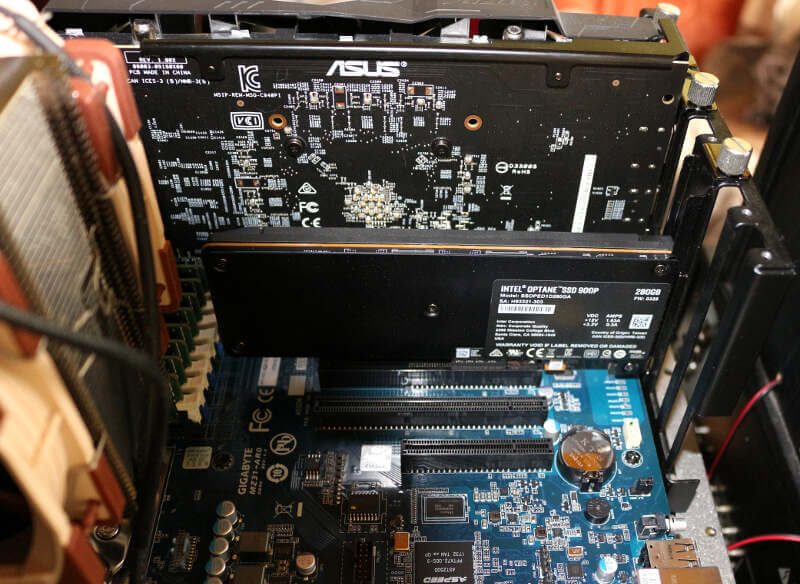
This isn’t an issue for most server setups, but it’s worth mentioning.
IO Area
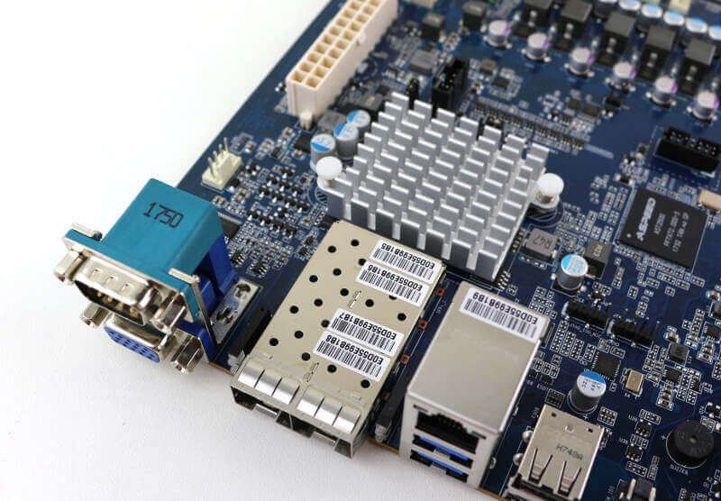
There aren’t a whole lot of connection options, because you don’t need a lot. From left to right, you get a COM port, a D-Sub VGA port, two 10GbE SFP+ ports, a Gigabit Ethernet management port, two USB 3.0 ports, and two USB 2.0 ports. The button all the way to the right is for identification and location purposes.

The 10GbE LAN controller is placed directly behind the ports and it is well-cooled thanks to the added heatsink.
Other Headers and Onboard Connectors
The onboard headers and connectors are located at the bottom side, starting with the serial COM header.
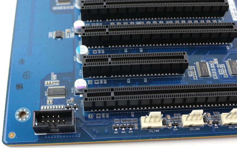
Next to that, you get four 4-pin FAN connectors and the USB 2.0 and 3.0 headers.
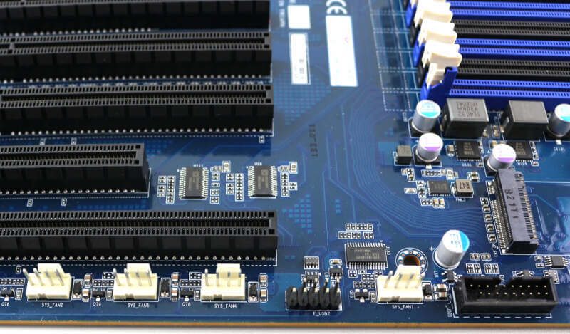
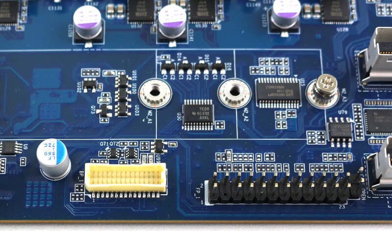
The backplane header follows those before we get to the frontpanel header. And that’s it. A realy simple setup without a lot of not-needed extras.
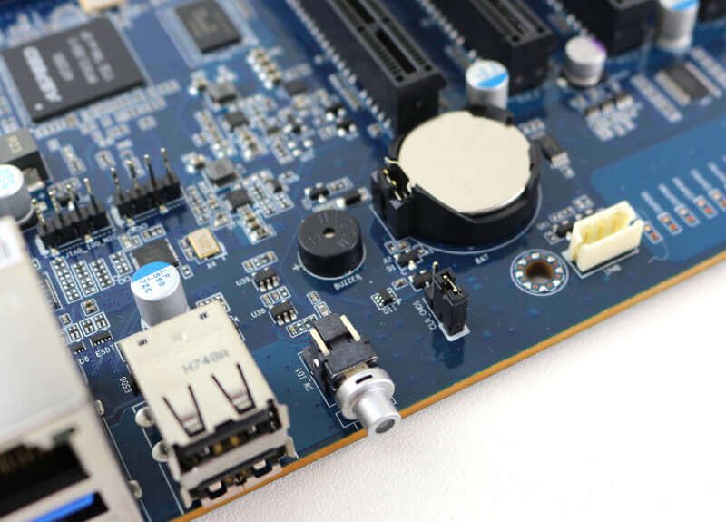
The BIOS battery and header, as well as the on-board speaker, are located at the rear side, close to the IO area.
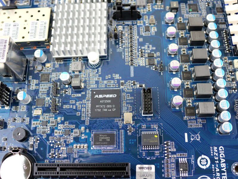
The only thing left to show is the TPM connector next to the Aspeed AST2500 controller. We can also spot the SKHynix memory for it right below.
