Gigabyte Z590I AORUS ULTRA Motherboard Review
Ben Enos / 4 years ago
A Closer Look
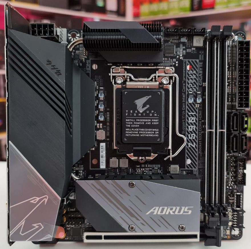
As we would expect with such a small board, there is so much going on and very little free space on the board. Even with all this crammed onto a 17x17CM board, Gigabyte has not cheeped out on any of the components used. Again, we are also seeing a mainly black board with some grey accenting which does look good. We can also notice a bit of extra armour around the PCI and RAM slots to provide that extra bit of durability.
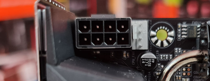
There is a single 8-pin EPS connector. ITX boards are not generally known for their overclocking ability, but you should still be able to achieve some mild results should you want. Right next to this, we have the CPU FAN header.
Across the board, we have three fan headers. Now you will notice these are not your standard 3 or 4-pin headers. That is because Gigabyte has included adapter cables for these. Whether this was to save space on the board or make it easier to install system fans once the motherboard has a cooler on it is anyone’s guess. All I can say is if you plan on using these, it will be easiest to just install the adapter cables from the beginning before you install the CPU cooler and RAM.
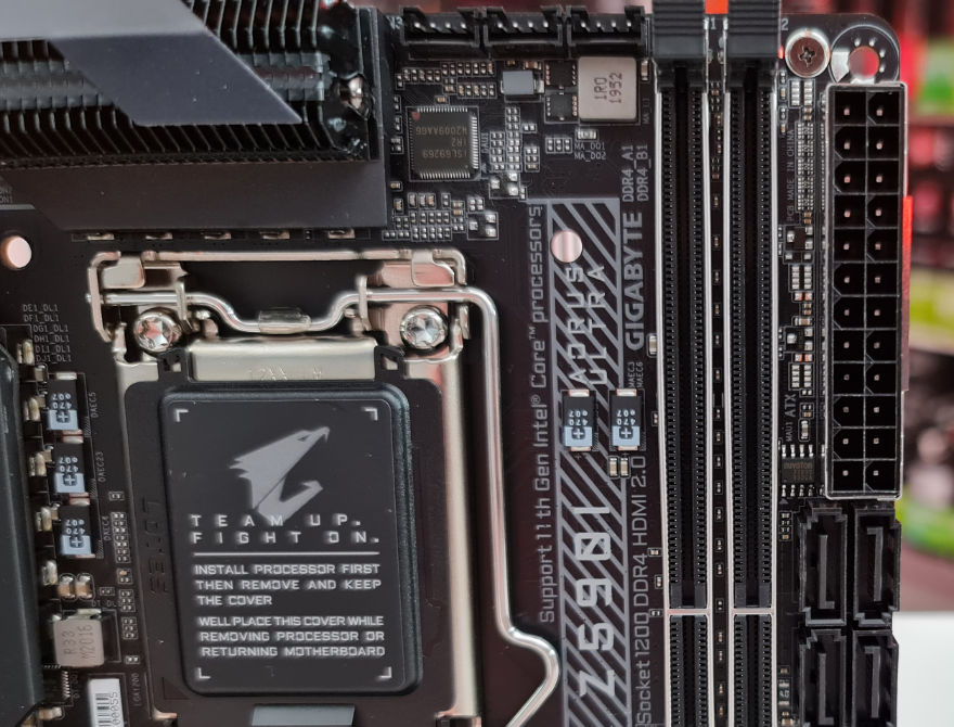
Gigabyte has gone with a 10+1 Power Phase design with 90A Phases. This will help to deliver higher efficiency of power and also result in lower temperatures. Gigabyte has also gone with a 10-layer PCB on this board that is said to also aid in the power delivery and heat dissipation. One of the extra PCB layers is just for power delivery and the other is a ground that will help to improve signal integrity.
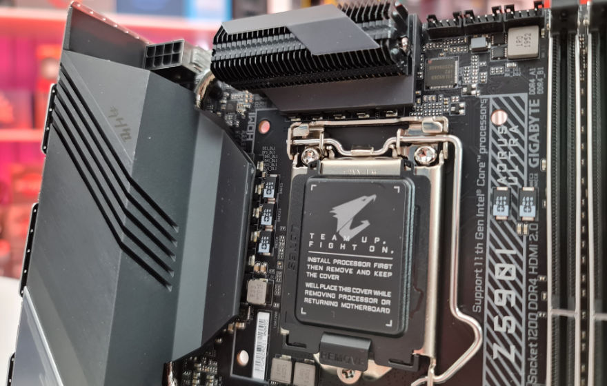
Between the M.2 shield and the rear IO shield we have a single ARGB header and our front audio connectors. THE PCIe slot has extra shielding on it to make it more durable and be able to handle even the heaviest of graphics cards. Gigabyte says this makes it 1.7x strong than without, which is good to know. The shield also has some extra anchor points on the other to help with the extra durability. Under this M.2 shield is where you will find your PCIe 4.0 slot for those super-fast NVMe speeds when using a compatible drive.

On the rear IO we have:
- 1 x DisplayPort
- 1 x HDMI port
- 1 x USB Type-C® port, with USB 3.2 Gen 2×2 support
- 3 x USB 3.2 Gen 2 Type-A ports (red)
- 2 x USB 3.2 Gen 1 ports
- 2 x USB 2.0/1.1 ports
- 1 x Q-Flash Plus button
- 1 x RJ-45 port
- 2 x SMA antenna connectors (2T2R)
- 3 x audio jacks
The Q-Flash Plus button is going to update the BIOS without the need for a CPU. This will come in handy should you want to get the board prepped and ready while still waiting for your CPU.

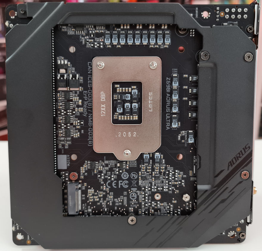
Not only does the back of the board house our PCIe 3.0 M.2 slot, but we can also see it has a lot of armour. This is going to help make the board more sturdy and make sure that it has no issues with holding the heaviest of graphics cars and/or CPU coolers.
