Supermicro X11SRA LGA2066 C422 Motherboard Review
Bohs Hansen / 6 years ago
A Closer Look & Layout Analysis
We had a look at the general feature on the first page and now its time to take a closer look at where everything is located.
Design wise, the Supermicro X11SRA is a very classic board, but that doesn’t mean that it isn’t packed with the latest of technologies. It is sized in a standard ATX form factor with the various headers and connectors located where you’re used to finding them.
Power Connectors and Processor & Memory Sockets
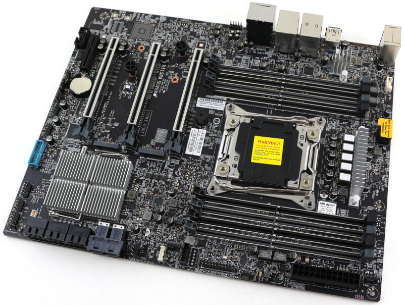
We get a single 8-pin CPU and a 24-pin power connector, making the motherboard compatible with as good as any power supply. We’ve recently seen motherboards with as much as three 8-pin power connectors, but not so here. The classic design is enough for this kind of system.
The processor socket and memory slots are also located in a default location, right at the top of the board. Consumers might see the four extra DIMM slots as unusual, but it’s normal for workstation boards. We can also spot the VRM and associated heat sinks.
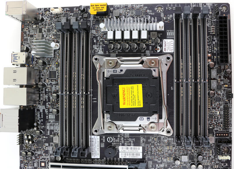
The LGA2066 CPU socket is located in a square-ILM cooler mount. While it’s no problem for me whether it’s a narrow or square ILM, it can make a difference for some CPU coolers. The square has the highest compatibility rate which again speaks for the ease of usage of the X11SRA.
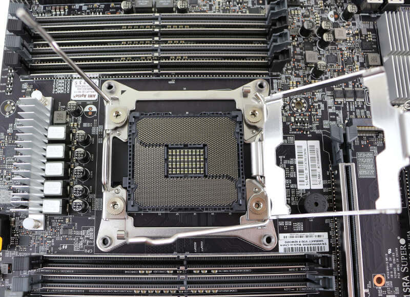
The eight DDR4 DIMM slots are reinforced which makes them sturdier as well as giving them a great look. With a full module setup, the board supports up to 512GB.
PCIe Expansion Slots
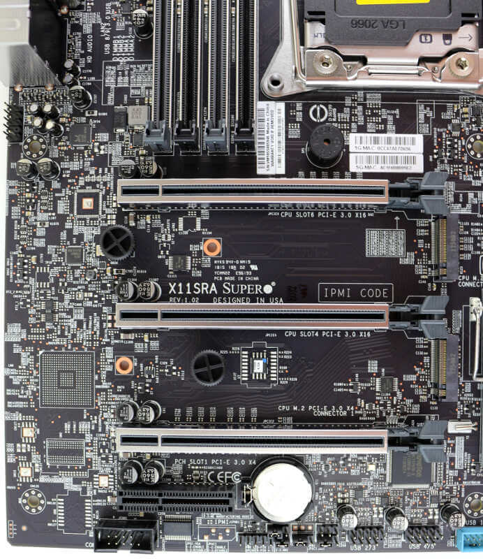
Moving down to the X11SRA’s expansion slots and we see the classic design continuing. You get three PCIe x16 slots which are reinforced for sturdiness and looks. The reinforced slots help when you install heavy add-in cards. Below the three PCIe x16 slots is a single PCIe x1 slot which isn’t reinforced as the other ones are.
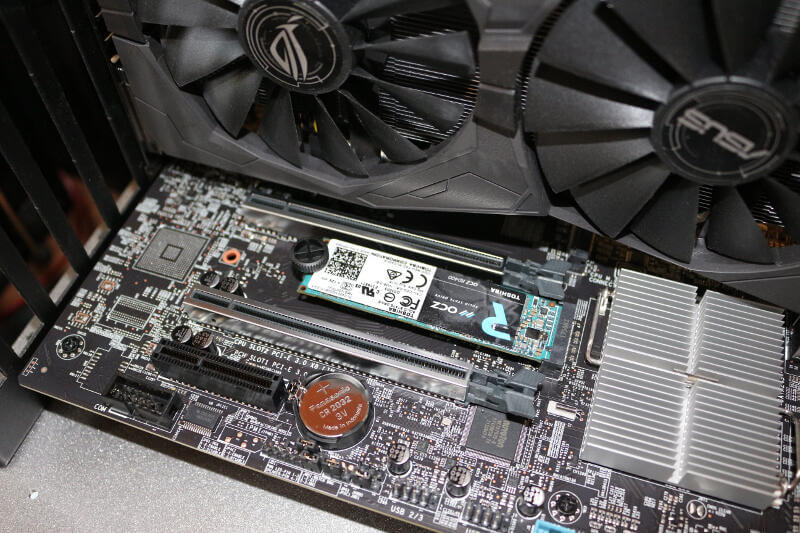
In between the PCIe slots are the two 32Gbps x4 PCIe M.2 slots with support for up to 22110 modules. The most common M.2 form factor is the 2280-sized, and they’re supported too. But nothing smaller. The M.2 slots don’t come with a screw lock as usual, but rather with a simple tool-less locking system. The plug can easily be pulled off to install the module and then pressed down again to secure it. I like this setup as it makes the M.2 installation a lot quicker. I tend to fumble with these tiny screws and my sausage fingers.
This is how it looks when a module is installed, so there isn’t any difference other than the method of securing the module to the motherboard.
Storage Connectors and Headers
The rest of the storage connectors are located at the inner bottom corner, again, as we’re used to. There are six SATA3 ports and two 32Gbps U.2 connectors. Together with the M.2 slots and extra possibilities from add-in cards, you can build a serious storage system.
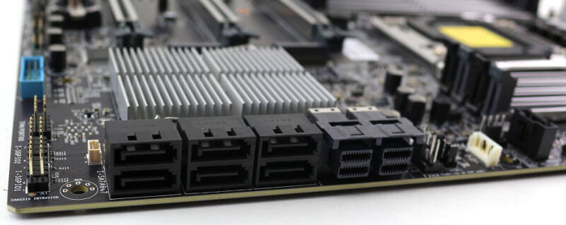
Most of the various headers, including the USB, are located at the bottom of the motherboard. This is also where you’ll find the TPM and SGPIO headers as well as the BIOS battery.

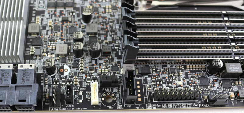
The front-panel header is at the top, next to the power connector. The pin assignment is printed on the PCB too, making it possible to set it all up without looking in the manual.

There are a total of five FAN headers which all are around the top area of the motherboard. It’s rare with bottom-mounted fans and more likely with front, and top mounted. With that in mind, it makes sense to place all the fan headers near the top of the motherboard.
IO Area
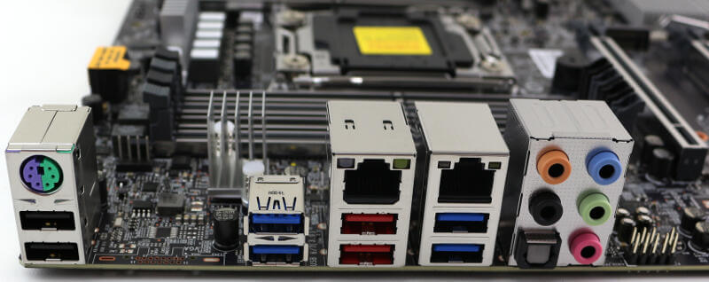
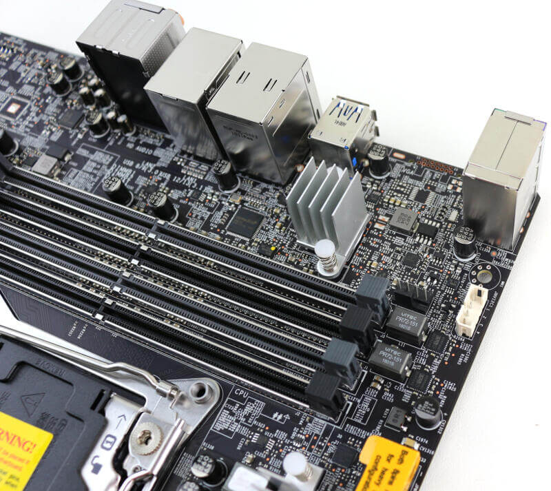
Last but certainly not least, we have the IO area. From left to right, we start with a combination PS2 keyboard and mouse port on top of two USB 2.0 ports. Everything you need for legacy support. Moving on, we find four blue USB 3.0 ports and two red USB 3.1 ports. On top of the USB ports are the two LAN ports. One is powered by an Intel PHY i219LM, and the other is a brand new Aquantia AQC108 5G multi-Gigabit LAN controller. All the way to the right are the audio ports. Next to them, we also see the front-audio header.
